Trench Drain Supply - 5621 Raby Road - Norfolk, VA 23502
http://www.trenchdrainsupply.com - Sales 877-903-7246 Ext 1

Trench Drain Installation Summary
These trench drain installation instructions are applicable to most installations. System designers must determine whether site conditions have special requirements regarding trench drain channel installation.
1. DRAINAGE SYSTEM DESIGNThe drainage system selected must be suitable for the customer’s application and for the location where installation is to take place.
2. PREPARATION
Read all information for your type of installation before starting
project. Collect tools and supplies needed to do the job. See list
of suggested tools and supplies in thedetailed
installation instructions.
3. EXCAVATION
Excavate trenches to a width and depth sufficient to ensure that
there is room for the minimum required thickness of concrete to be
placed under and alongside the channels. Remember that the pavement
surface next to the channels must be laid so that it is 1/8 in. (3
mm) above the top of the channel.
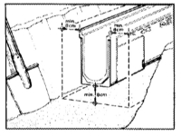
4. CHANNEL LAYOUT
Lay out channel system parts in the planned sequence alongside the
excavated trench according to the installation plan. Ensure that
channels are placed in the proper position and in the proper
direction. Set outlet channel first (highest channel number),
5. KNOCKOUT REMOVAL
Remove preformed knockouts from channels and catch basins for
required piping connections.
6. INSTALLATION AND BRACING
Begin installing channels at the downstream discharge end of the
drainage system. Install and brace channels so that channels will
remain in place without sagging prior to pouring concrete and so
that channels will not float out of position during or after pouring
concrete. Channels must also be braced against any side loading that
would prevent easy installation of grates after the concrete sets
up.
7. POURING CONCRETE
Do not bump or jar channels out of alignment during the pouring of
concrete. Pour concrete slowly enough to ensure that channels do not
float out of alignment and do not pour concrete directly against
channels. Pour the same amount of concrete on both sides of channels
to avoid pushing channels out of alignment. The pavement surface
next to the channels must be laid so that it is 1/8 in. (3 mm) above
the top of the channels.
8. CLEANUP
Clean any spilled concrete from grates, channels and outlet points.
Insert and secure grates to channels using the optional locking
devices.
Preparation
1. DRAINAGE SYSTEM DESIGN
The drainage system selected must be suitable for the customer’s
application and for the location where installation is to take
place. The carrying capacity of the subsoil and the strength of the
trench floor must be considered. Consideration should also be given
to the use of expansion joints in both longitudinal and transverse
directions to minimize horizontal forces which would distort the
channel system.
2. PREPARATION
Read all information for your type of installation before starting
project.
Collect tools and supplies needed to do the job. The following may
be useful for your installation:
| Shovel | Screwdriver | Wooden or steel stakes |
| Level | Saw with masonry or diamond blade | Grout and adhesives* |
| Square | Grinder | 2” x 4” boards |
| Chalkline | Caulk gun and caulk sealant* | Plywood |
| Large hammer | Vibrator | Gloves |
| Cold chisel | Drill and masonry bits, about 3/8 in. (10 mm) diameter |
Respirator |
| Safety glasses or goggles | 3” schedule 40 PVC pipe |
*Selection of Caulks, Grouts and Sealants:
Adhesives, caulking compounds, grouting and sealants used on the
drainage system must be compatible with all chemicals that will flow
through the system. Openings and joints may be filled with one of
several materials. Silicone caulk should be used when a flexible
joint is needed. A two-component epoxy grout should be used when a
rigid joint is needed. A fast setting cement type grouting compound
may be used where high durability is not needed.
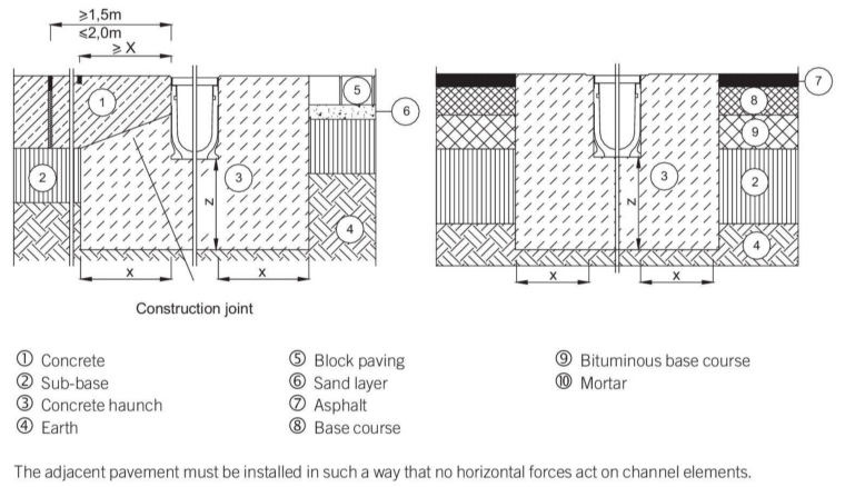
EXCAVATION
Example Installations:
Load Class A
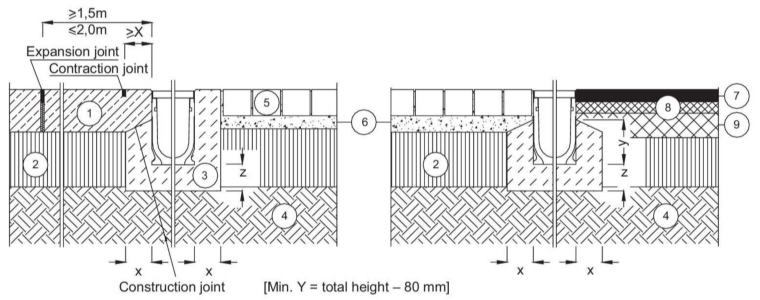
Load Class B
NEXT: Channel Layout
CHANNEL LAYOUT
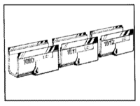
4. CHANNEL LAYOUT
Lay out channel system parts in the planned
sequence alongside the excavated trench according
to the installation plan. Ensure that channels are
placed in the proper position and in the proper
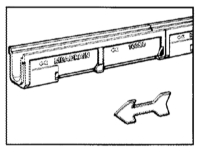
direction. The number on the side of each channel
shows the position of the channel within the drainage
line. The direction of flow is shown by arrows on the
channel sides which point to the outlet.
5. KNOCKOUT REMOVAL
Drill holes around the perimeter of knockout breaking
point using a masonry bit about 3/8 in. (10 mm)
diameter. Carefully remove the knockout from inside
the channel using a hammer and cold chisel. Clean
up edges of hole using a hammer and cold chisel or a
grinder. Invert channel and insert outlet connector
from bottom and apply sealant. Allow proper time for
sealant to set before handling. Catch basins and outlet channels contain preformed
cutouts for piping, channel and catch basin conn. Remove these knockouts only as needed.

CAUTION Knockouts should be removed carefully in order to prevent cracking of the channel around the knockout hole.
WARNING
Wear protective eyeglasses or goggles, a respirator mask and gloves
when cutting, chiseling, drilling or grinding concrete or asphalt.
Avoid breathing concrete and asphalt particles since they could be
harmful to your health. Observe all safety precautions
when operating electrical or hand
tools.
NEXT : Installation and Bracing